
Tallahassee -- July 2003
Bosch 4-Wire Oxygen Sensor Upgrade
September 2003
Tallahassee -- July 2003
Bosch 4-Wire Oxygen Sensor Upgrade
September 2003
What the heck is a 4-Wire O2 Sensor?
![]() How
does a Platinum/Zirconia O2 Sensor work?
How
does a Platinum/Zirconia O2 Sensor work?
![]() Testing a Platinum/Zirconia O2 Sensor?
Testing a Platinum/Zirconia O2 Sensor?
|
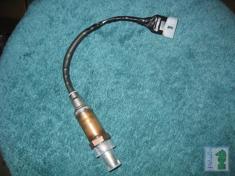
I recently installed an OBX 4-2-1 header, purchased through eBay for $175 delivered, on my 1990 Miata (including a new single wire O2 sensor). Although I was not disappointed, I was somewhat under-whelmed by the power gains and confused by the inconsistencies of the power delivery (I was also at the same time pleased that I hadn't spent more for a "name brand" header). After a 1000 miles or so, and as the novelty wore off, I began to notice a definite surging when the engine was not fully warmed up, and uneven power delivery and a real burst of power at 4000 RPM during hard acceleration once it was warm. Some research revealed this to be related to the operational needs of single wire oxygen sensors, so I set out to find a suitable 4-Wire Sensor. Autozone had the Bosch p/n 13275 sensor I had seen mentioned on Miata.net and elsewhere for $34.99 (1/2004, it's $39.99 now), so armed with my trusty VISA card off I went into the fray. This sensor is an OEM replacement for some mid-90's Chrysler products, and comes with a very nice male connector, and pre-loaded with anti-seize compound. I installed the same BOSCH sensor included in this kit and on my first trip "around the block" I found dramatic improvement in power delivery and the overall smoothness of the engine. During a 400 mile road trip the next day I was sold--this is what I expected a high performance header to do for me!!! Wanting to share my joy with the world I put together this Plug 'n Play 4-Wire Oxygen Sensor upgrade page... |
|||||||||||||||||||
|
1. |
2.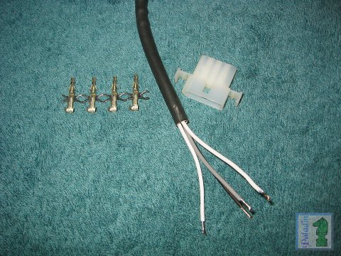 (click for a larger image) |
3. (click for a larger image) |
4. (click for a larger image) |
||||||||||||||||
|
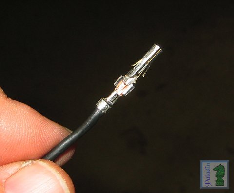
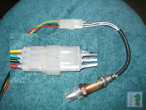
Picture 1. shows the Bosch 13275 O2 sensor as removed from the box. Photo 2. shows it with the supplied connector cut off, the leads trimmed, and introduces the Radio Shack p/n 274-224 4-pin Molex style male power connector ($1.49). Picture 3. shows a properly crimped terminal (you need to cut the terminals apart, leaving a couple of little "flags" that will retain it in the connector body)--photo 4. shows the terminals being inserted into the body. They will snap into place, you will have to crimp the "flags" a bit to get them to fit into the connector body. |
|||||||||||||||||||
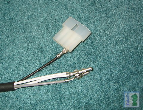
5. (click for a larger image) |
6. (click for a larger image) |
7. (click for a larger image) |
8. (click for a larger image) |
||||||||||||||||
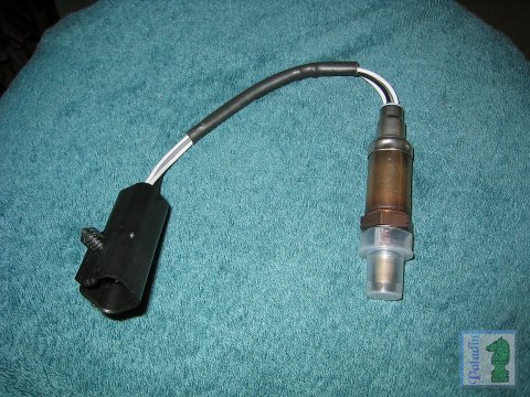
Photo 5. shows the O2 sensor with the connector fully in place (the insert in photo 8. shows the epoxy bedding I use in assembling the kits I've made for others--it's not 100% needed, however I would use some dielectric grease or something however). Picture 6. shows the O2 sensor completed, with a double wrapping of harness tape to make it ship-shape. Picture 7. shows the female counterpart Molex connector (RS p/n 274-234), and photo 8. shows the assembled potted connectors, sensor and harness. I use 16 ga. heat resistant automotive grade wire in red (70"), black (68"), green (36"), and yellow (28") for the harness. The red and black wires go to female connector's #3 and #4 terminals (the "pointed" end is #1) and through to the sensor's white leads (the sensor heater's power) via the male connector; The green lead passes through the connector #2 terminal to the sensor's gray (O2 signal ground) lead; And the yellow
lead goes through the #1 connector terminals, to the sensor's black
(O2 signal output) lead. |
|||||||||||||||||||
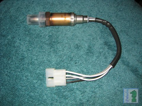
9. (click for a larger image) |
10. (click for a larger image) |
11. (click for a larger image) |
12. (click for a larger image) |
||||||||||||||||
|
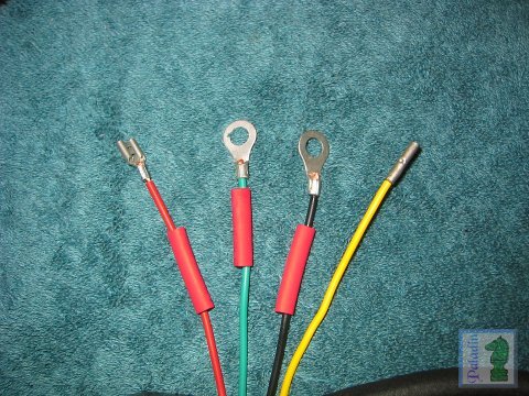
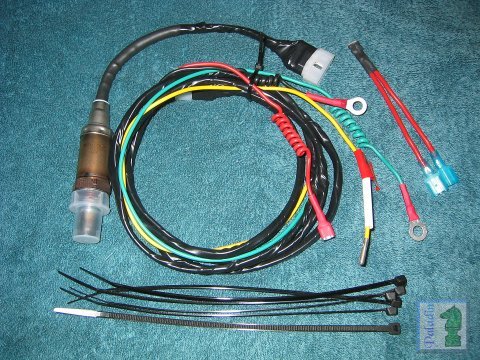
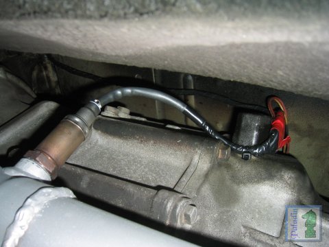
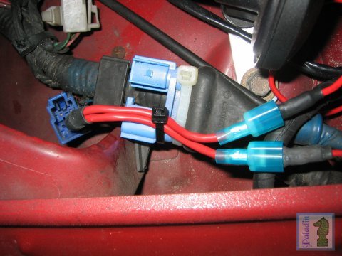
Picture 9. shows the end terminations I use. The red wire (sensor heater 12V+) terminates with a 1/4" female spade connector, to connect to the blue "test" power connector behind the left headlight; the black wire (sensor heater ground) and the green wire (O2 signal ground) each have a 1/4" eye terminal; last, the yellow wire (O2 output) has a 16-18 ga. crimp type barrel connector. These are all insulated using heat shrink tubing, the yellow wire's connector being shrunk up during installation. Photo 10. shows the complete "Plug 'N Play" kit I have put together for some friends. Picture 11. shows the O2 sensor installed into my OBX header. Photo 12. shows the connection to the blue diagnostic power connector using a custom "Y" connector which let's me use a timing light AND have the O2 sensor connected too (I also steal power from here for my fog light relay coil--this means they shut off when the key is not in the RUN position). If you make up this kit as shown, these installation instructions will explain how to hook it up. |
|||||||||||||||||||
|
How
does a Platinum/Zirconium O2 Sensor work?
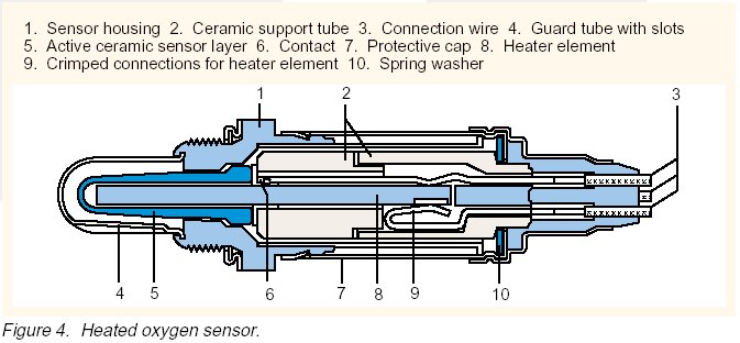
A Platinum/Zirconium dioxide (P/Z) oxygen sensor is a galvanic oxygen concentration cell that uses a solid state electrolyte of impermeable zirconium dioxide ceramic unit stabilized with yttrium oxide (item 5 in Figure 2), the sensor element is open to the atmosphere on one end and closed on the other. Mounted on both the inner and outer surfaces of the ceramic core are gas permeable platinum electrodes. The platinum electrode on the outside acts as a catalyst to support reactions in the incoming exhaust gases, it also has a porous ceramic layer to protect against contamination. The inner cavity is open to the atmosphere which serves as the unit's reference gas. They operate electrochemically, on the Nernst principle [Walther H. Nernst (1864-1941)]. When the ceramic electrolyte is heated to 350°C or higher it conducts oxygen ions. Then, since one porous platinum electrode is exposed to the atmoshere and the other to the exhaust gasses, the differences in ionic density of the gasses on either side of the electrolyte want to come into equilibrium--this "balancing act" creates an ion flow from the atmospheric air through the ceramic and into the exhaust gasses. It is this ion flow through the ceramic that produces the measurable voltage. This also means that the polarity of the output voltage is not fixed. We humans and the ECU see it that way since atmospheric air always contains more oxygen than exhaust gasses--however if it were possible to apply exhaust gas to the (very small) port that's normally open to the atmosphere, and have the "tip" immersed in ambient air, the polarities would reverse. P/Z O2 sensors do NOT detect the presence of oxygen. What they do is generate a voltage related to the difference in the oxygen content of the atmosphere and the exhaust gas. They are basically two-state devices, capable only of telling the ECU when the fuel mixture is rich or lean (more about this below), and they do nothing at temperatures below 662°F (they become the electronic equivalent of a very high value resistor (think hundreds of megohms), the ideal operating temperature is 950°F or higher. So as the amount of residual oxygen in the exhaust (always less than the sensor's reference) changes in response to variations in the induction mixture's air/fuel ratio the sensor's output varies from 0.8V to 1.0V for rich mixtures to as low as 0.1V for lean mixtures. At the ideal air/fuel ratio of 14.7:1 (know as a stoichiometric mixture ) the output is 0.45V to 0.5V, however... It is very important to understand that even very small variations away from the ideal A/F ratio will cause the sensor's output voltage to move into its lean (or rich) levels--this is why they are called narrowband sensors. Additionally they are only capable of producing any meaningful signal, at all proportional to the exhaust gas' oxygen content, in a relatively narrow range of air/fuel ratios from about 11:1 to 17:1 (see Figure 1). Think of a narrowband O2 sensor as a switch that changes it's output from low to high and back each time the air/fuel ratio changes from the ideal 14.7:1 mixture. The ECU uses this signal by accumulating the average of multiple readings and constantly adjusting the fuel injector duty cycle (how long they are open) to keep the average of the sensor's voltage readings at 0.45V. This is why failing and even failed O2 sensors do not trigger an immediate error code. The ECU has to monitor the sensor in closed loop mode for a period of time before is can recognize that it's output is not changing, or not changing sufficiently fast enough or within the proper range. This can take as much as 3-5 minutes of steady speed driving. A steady speed is needed to ensure the ECU stays in closed loop mode long enough to get a clean average reading--it needs this to tell if the sensor is good or not--driving at other than a steady speed (like around town) forces the ECU to change in and out of closed loop mode as you accelerate and decelerate, each transition resets the averaging accumulator. It is also this manner in which the ECU has to use a P/Z O2 sensor's signal that causes a completely failed or even disconnected sensor from producing an immediate error code. A cold O2 sensor has such high resistance that for all practical purposes it's the same as the open circuit of a completely failed or disconnected unit, the ECU has to wait until it's sure the sensor is not producing any useful signal before it can be certain it's dead. In heated oxygen sensors an electric heater element (item 8 in Figure 2) is used to heat the ceramic material to 1000°F or so when the engine is operating at low load factors, at higher load factors the sensor is kept hot by the exhaust gas. A heated oxygen sensor helps ensure low and stable emissions and performance by consistently maintaining an optimal operating temperature. The heaters are typically in the 25W to 30W (2.0A to 2.5A at 12V) range, the same as a small soldering iron.
|
|||||||||||||||||||
| What
the heck is a 4-Wire O2 Sensor?
Platinum/Zirconium dioxide oxygen sensors (1, 3, or 4-wire) require that they be heated to a minimum of 662°F before they will produce any output signal (below this critical temperature they behave as a fairly large value resistor), and need to be in the range of 975°F to 1200°F to be operating optimally. This creates a problem when the sensor is located too far from the exhaust ports, or relocated further "downstream" from the exhaust ports as is common with most if not all aftermarket headers designed for the early Miata. Heated O2 sensors (requiring 3-wires) were designed to keep the sensing element heated to it's optimal temperature--the 4-wire sensor adds the benefit of a dedicated output signal ground wire (1 and 3-wire sensors use the exhaust system as the signal ground path). With my 4-2-1 OBX header (an unashamed clone of the Racing Beat 4-2-1 design) the O2 sensor is located over 18" further from the exhaust ports than with the OEM header. This means that at times of low engine output such as idling and low power acceleration the sensor's temperature can drop out of the optimal range, and even below the functional range--this results in the ECU thinking that the engine is running lean. The ECU then compensates for what it thinks is a lean mixture by making the air/fuel mixture richer (more fuel) to what is really an overly rich mix; causing bogging and at times an actual "flame out" as the over-rich mixture won't ignite. Heated (4-Wire) O2 sensors overcome this problem by including a 12V electric heating element (#8 in this diagram) within the sensor. These heating elements (typically 25W or so) keep the sensor heated to 1100°F or and therefore smack in the middle of it's optimal operating range. |
|||||||||||||||||||
|
Testing a Platinum/Zirconia O2 Sensor?
Use a DC voltmeter set to a 0-1V or 0-2V scale, then...
Bear in
mind that good and bad is relative to your particular ECU's needs.
Any O2 sensor that will generate 0.9V or more when heated,
For heated (3 and 4-wire) sensors check
the resistance across the heater power and ground leads; When
replacing a sensor, don't miss the opportunity to use this test
sequence on the replacement. There is almost always no benefit in replacing an oxygen sensor that will pass this test procedure. |
|||||||||||||||||||
Return/Goto My Miata Home Page

Persian mythology gave the name Ahura Mazda
to the god of light...
cliffyk@paladinmicro.com

