Chimney Rock, NC -- October 2002
BRB/Ignition Information
December 2002--Updated January 14, 2004
The Miata Ignition System (why cheap, black plug wires don't work)
Chimney Rock, NC -- October 2002
BRB/Ignition Information
December 2002--Updated January 14, 2004
The
Miata Ignition System
(why cheap, black plug wires don't work)
| I've read reports of people having problems with their BRB modifications failing after a short time. Many of those reporting such failures have said they used relays from discount auto parts chains, Radio Shack, WalMart, and the like. Here's what those Asian "el Cheapos" look like inside, and a comparison to a good one. | ||
|
|
||
| On the left is a typical 30 ampere (according
to them) SPST (Single Pole, Single Throw) Asian horn relay that came with
a cheap set of air horns. You can see that the actuating coil is
relatively small, and that the contact post is made of "thinnish"
brass. Note the size of the contacts, and the plastic coil form and fixed
contact support too. What you can't see here is that the copper
strip/spring for the movable contact is just crimped to the steel relay
frame (on the back). The steel frame upright is also the #30 common
terminal. This is a very low grade relay barely suitable for intermittent
use in a horn circuit, in an auxiliary lighting circuit it would probably
melt down in a week or two. It might work (for a while) in a BRB
installation, but I'd not trust my ride home to it. The SPDT (Single Pole, Double Throw)
relay you can order from Radio Shack and some parts stores is a bit better
than this, but not a whole lot. In the middle is a 40 amp SPDT relay from NAPA (their part # AR272, around $14). Note the larger coil (with larger wire), copper contact posts, larger contacts, and nylon coil form. It's obvious that the overall construction is superior (the movable contact strip/spring is spot welded to the relay frame, as is the copper #30 terminal. Also included in the design is a 680 ohm 1/4 watt resistor in parallel with the coil to shunt the reverse voltage spike that occurs when the coil is de-energised. This protects the activating switch from arcing (to some degree) and reduces radio frequency interference (RFI) from the same event. On the right is a NTE 40 amp relay (specifications) purchased from Mouser Electronics (their stock # 526-R51-5D40-12F, $7 each). This unit is potted (sealed, which is good) so I didn't want to break it open, however you can gauge by it's weight and 3 copper terminals for the relay contacts that it is of the same construction as the NAPA unit. It probably does not have the resistor in parallel with the coil as it is not specifically an automotive relay (RFI is a significant concern in automotive apps). It is nonetheless a very good relay that should prove reliable in extended use. NTE makes a 70 amp SPST relay (their # R51-1D70-12F) that is available from Source Research, Inc. for $10--this relay would be perfect for duplicating the IG1 switching functions of the manual ignition switch via an alternative control switch. SRI also stocks the 40A SPDT model for $8. If I was to choose (I did), I'd get the NAPA relay, or use the NTE relay with an externally mounted resistor. |
||
|
Note:
There are many 5-terminal automotive cube (AKA Bosch) relays out
there that are really SPST units, even though they have contact terminals
labeled 30, 87, and 87a. These are the ones typically sold by discount
auto parts chain stores and other consumer outlets for use in auxiliary
lighting, horn circuits and the like. On these units the 87 and 87a
terminals are both normally open contacts--using one of these in a
properly wired Miata BRB circuit will cause accessories powered by the IG2
circuit (wipers, cigar lighter, heater/AC, etc.) to not function.
You can check the diagram on the relay's case (if it has one), it should look similar to the SPDT pictorial below -or- check the continuity across terminals 30 and 87, and 30 and 87a--if both these paths are open then you've got a fake 5-terminal SPDT relay. |
||
|
|
|
|
|
Below are links to Adobe Acrobat (.PDF) files providing wiring diagrams for a simple BRB modification, a limited full replacement of the manual ignition switch's functionality using 4-relays, and a total replacement of the manual switch's functions using 5-relays. There's quite a bit to replacing all the functions of the manual ignition switch (MIS) with control
circuits. The MIS has two inputs and four outputs as follows: |
||
 Click to retrieve the schematic for a basic Big Red Button modification. |
 Click to retrieve the schematic for a limited replacement of the switch's functionality. |
 Click to retrieve the schematic for a total replacement of the ignition switch's functionality. |
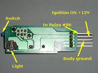
| Here are some photos of the inside of the Honda S2000 BRB. This switch uses both poles of a DPDT (Double Pole, Double Throw) switch to switch the relay, and to switch a diode across the relay positive terminal and ground when the button is released. This diode is installed so as to shunt the reverse EMF spike generated when the relay coil's field collapses to ground, thus preventing the switch contacts from arcing. By using both poles of the switch in parallel the current carrying capacity is nearly doubled, and there's a built-in sort of redundancy. A 3.5" floppy drive power connector makes a great connector for this switch--look here. | |
|
|
|
| The S2000 BRB internal photos are courtesy of Oichan who had the presence of thought to take it apart before installing it in his Volkswagon Corrado. | |
|
|
|
| These photos are from Bob Caruthers' M2 BRB Installation website, another fellow who took the time to document his work. | |
| This is what the innards of my ignition switch looked like when I decided that it was time to do something about having to fiddle with it to get the accessory (radio, etc) power on. 15 minutes, some WD-40, elbow grease, and a brass wire brush, later it was good as new! | |
|
Ever wonder why the Miata can eat up plain 'ol plug wires in 15K miles or
less? So did I after I had burned up my second set of Autozone's lifetime
warranted Double Silicone 7 m/m wires. After some research I found
that the DIS (Distributorless Ignition System) of the Miata, like many
DIS's, uses a non-conventional (as compared to a "distributored"
system) wasted spark method of connecting the spark coil output to
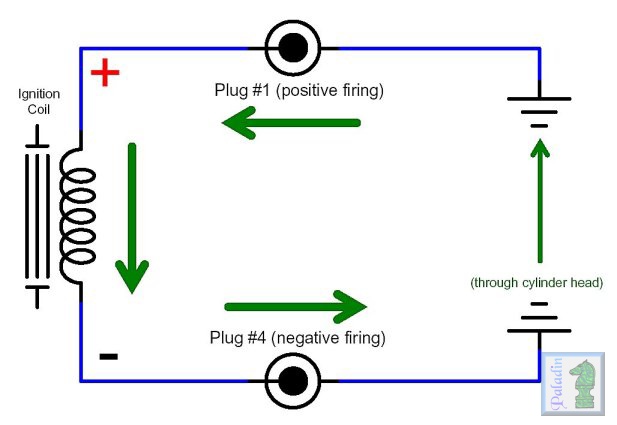
the plugs (many other automobiles now do this as well)--the diagram above
shows the primary (low voltage) and secondary (high voltage) sides of one
ignition coil, the cylinder #1 and #4 coil, and most importantly shows how
the spark plugs are connected to the secondary output. The wasted spark
part is that for each firing of the two plugs, one of them is firing at
the top of the exhaust stroke "wasting" it's spark.
As you can see, the lead wires from the plugs are connected to the two ends of the secondary coil windings, with the electrical path between the plugs being provided by the cylinder head (ground). What this means is that the ignition pulse--a DC pulse of some considerable voltage--travels from the lower coil terminal (as drawn), through the tip of #4 plug to the side electrode (making it spark), and then through the cylinder head to the body/side electrode of the #1 plug to the tip (making #1 fire), and finally back to the upper terminal of the coil. This means a couple of things relevant to the characteristics of Miata plug wires. The most obvious is that each plug wire needs to carry enough power to fire two plugs, whereas in a conventional "distributored" ignition system (or a DIS with a coil for each plug, or in which the output pulse is "split" and directed to two plus) each wire only needs to handle the load of one plug. The second and less obvious issue is that although the voltage differential between each plug wire and ground when they fire on the real cycle is that same as in conventional systems (typically 25,000 Volts or so), the voltages are of opposite polarity with respect to ground (at idle, during the #4 plug's real sparking event, the #4 circuit the spark pulse is 25KV below ground, in the #1 circuit it's probably 3KV above ground--no compression means less voltage needed to make a spark)--this makes the voltage differential between the plug wires higher than in a conventional ignition system, generally 28-30KV and potentially as high as 40KV when things start to wear down and at high RPM/WOT. So, if we take the additional power requirements, the higher inter-wire differential voltage, and then add some engine heat and vibration, and the fact that the plug wires run "side-by-side" it becomes easy to see why plain 'ol resistor wires (typically carbon impregnated latex coating a nylon or Kevlar core) can't hack it--and why our Miatae run so miserably once the plug wires break down from the added work. I suspect that we get weaker sparks at first as the resistance of the wires increases (I understand that the carbon particles "burn out", increasing wire resistance) and they can't fully cope with firing two plugs, and that eventually some loss of spark energy occurs as the opposite polarity voltages in the two wires begin to find the path through the wire insulation to the coil preferable to the path through the plugs. Spark Plugs: Conventional spark plugs are designed with this in mind, and the center electrode (the "tip") is made from a material less susceptible to erosion from the electron flow. This means of course that when the polarity is reversed it is the side electrode that is eroded--which may or may not be designed for that consideration. My understanding is that this is much more pronounced in platinum tipped plugs (probably only because of their longer service life)--this is why nearly all plug manufacturers now make some flavour of double platinum plug that have both a platinum tip, and a platinum insert in the side electrode. Many manufacturers actually save a buck or two per car by using plugs with only one platinum electrode (on the tip or side as required) in the OEM plugs. |
|
Other BRB/Ignition links
Adam Wolfe's M1 BRB installation
Keith Tanner's M1 BRB installation
Bill Keksz' M1 BRB installation
Handa-Accessories S2000 OEM BRB
A nice white paper about platinum plugs and DIS
Ignition and spark plug tech facts--about the 3000GT/Stealth, but applicable to our guys too
DIS Waveform Analysis (Excellent)
Miata Wiring Diagrams (1990-2000)
![]()
Return/Goto My Miata Home Page
Persian mythology gave the name Ahura Mazda
to the god of light...
cliffyk@paladinmicro.com